11 Digital Communications - I2C
This chapter is based on the projectlet:

- 09_i2c

and supported by:

- 98_Utils/09_i2c
11.1 Projectlet Goals
Exploration of digital communication discipline using USARTs exposed a significant weakness - the fact that there is no clock or timing as part of the physical layer. This could lead to inconsistencies between the cooperating devices. The invention of protocols such as Inter-Integrated Circuit and other similar derivatives (e.g. I2S, smbus) addressed this challenge amazingly well; these protocols have become an essential part of most embedded systems for integrating sensors, actuators and the like.
The architecture has further benefited from the qwiic ecosystem with standardized connectors and the large number of devices. In this projectlet, 2 such devices - a temperature sensor and a digital display are integrated with our microcontroller.
In addition the binary logging discipline developed earlier is applied to transmit the temperature feedback to a (presumably) supervisory level system. Examples of receiving these packages, unpacking using the nanoprotobuf library completes the system.
11.1.1 The roadmap
At a high level we will build the system to the following architecture.
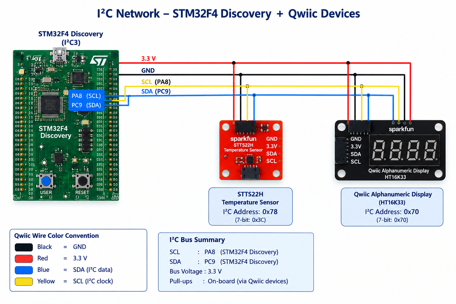
The temperature sensor will be used to measure the ambient temperature. The temperature converted into centigrade and timestamped will be transmitted over a binary serial interface.
The display is primarily an output device, used as a rotating display of alphanumeric characters or as a minute, second clock.
I2C being an extensible network, additional sensors or other compatible devices can be added with ease.
Further to form a complete system we will add a higher layer system, connecting to the microcontroller using the Serial protocol.
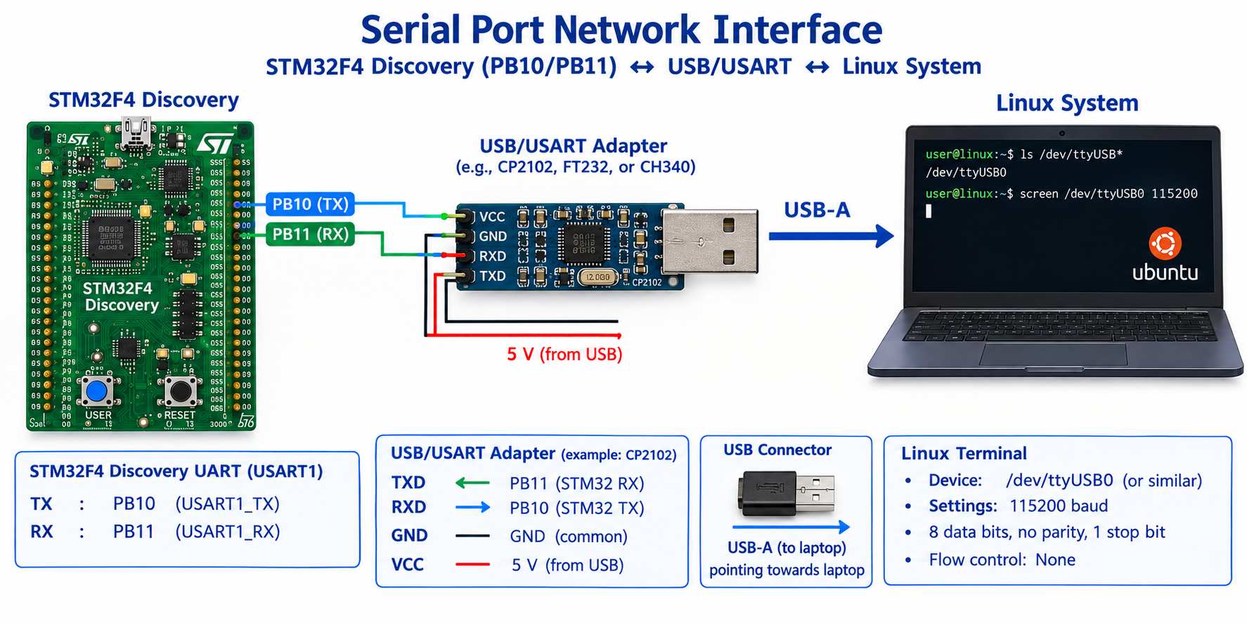
The serial interface will be used to transmit the temperature readings packed into a nanoprotobuf packet. The host will then receive the binary data, unpack and print out the temperature. It is of course feasible to have the host be on the I2C network; most real life devices prefer this approach or an ethernet network to integrate the supervisory systems.
11.2 Sensor Network
The microcontroller serves as the master of our I2C sensor network. The controller interacts with each of the nodes of the network as the application demands. The base protocol dictates the line discipline and the steps of reading and writing.
File : toolkit-i2c.adb

0034 |    procedure Attach is
0035 |       cfg : stm32.i2c.I2C_Configuration;
0036 |    begin
0037 |       pragma Debug (stm32.GPIO.Set (stm32.board.Blue_LED));
0038 |       Enable_Clock (GPIO_A);
0039 |       Enable_Clock (GPIO_C);
0040 |       Enable_Clock (I2C_3);
0041 |       Init_I2c3_GPIO;
0042 |       cfg.Clock_Speed := 100_000;
0043 |       cfg.Mode := stm32.i2c.I2C_Mode;
0044 |       cfg.Addressing_Mode := stm32.i2c.Addressing_Mode_7bit;
0045 |       cfg.Own_Address := 0;
0046 |       stm32.i2c.Configure (stm32.Device.i2c_3, cfg);
0047 |       stm32.i2c.Set_State (stm32.Device.i2c_3, true);
0048 |    end Attach;
The microcontroller utilizes one of the I2C devices on the board (I2C3) and sets itself up as the master of the network as shown above. The master then determines the data rates 100 Kbps as indicated above. Since the clock is part of the wire, the sensors dont get to choose the speed though not all sensors may be able to support the data rates depending on their function.
Once attached, reading and writing become pretty straightforward given the extensive support provided by the ADL through the packages stm32.i2c.
File : toolkit-i2c.adb

0052 |    procedure Read
0053 |      (stat   : out hal.i2c.I2C_Status;
0054 |       addr   : hal.i2c.I2C_Address;
0055 |       reg    : hal.UInt16;
0056 |       result : in out hal.i2c.i2c_data)
0057 |    is
0058 |       Status : hal.i2c.i2c_status;
0059 |    begin
0060 |       stm32.i2c.Mem_Read
0061 |         (This          => port,
0062 |          Addr          => addr,
0063 |          Mem_Addr      => Reg,
0064 |          Mem_Addr_Size => HAL.I2C.Memory_Size_8b,
0065 |          Data          => result,
0066 |          Status        => status);
0067 |       stat := Status;
0068 |    end Read;
and for writing:
File : toolkit-i2c.adb

0072 |    procedure Write
0073 |      (stat : out hal.i2c.I2C_Status;
0074 |       addr : hal.i2c.I2C_Address;
0075 |       reg  : hal.UInt16;
0076 |       data : in out hal.i2c.i2c_data) is
0077 |    begin
0078 |       stm32.i2c.Mem_Write
0079 |         (port,
0080 |          addr,
0081 |          Mem_Addr      => reg,
0082 |          Mem_Addr_Size => HAL.I2C.Memory_Size_8b,
0083 |          Data          => data,
0084 |          Status        => Stat);
0085 |    end Write;
Each member usually has its own extensive specifications to be found in the data sheets.
11.2.1 Temperature Sensor stts22h
The stts22h temperature sensor, simple though it may seem, has an elaborate datasheet based on which the initializations, configurations are to be achieved before data acquisition. The raw data acquired may require further processing eg in this case conversion to centigrade before applications can utilize those values.
With the toolkit support above, the specific sensor is initialized:
File : stts22h.adb

0072 |    procedure Setup (stat : out hal.I2C.I2c_Status) is
0073 |       CTRLVAL : constant :=
0074 |         SETGET_CTRL_FREERUN + SETGET_CTRL_IF_ADD_INC + SETGET_CTRL_AVG0
0075 |         + SETGET_CTRL_AVG1;
0076 |       pkt : HAL.I2C.I2C_Data (1 .. 1);
0077 |    begin
0078 |       pkt (1) := CTRLVAL;
0079 |       toolkit.i2c.Write (stat, addr, REG_CTRL, pkt);
0080 |    end Setup;
and the feedback read:
File : stts22h.adb

0045 |    function Read (stat : out hal.i2c.I2C_Status) return Temperature_Type is
0046 |       rawresult : hal.i2c.i2c_data (1 .. 2);
0047 |       result    : Temperature_Type;
0048 |    begin
0049 |       toolkit.i2c.Read (stat, Addr, REG_TEMP_L_OUT, rawresult);
0050 |       result :=
0051 |         Temperature (Unsigned_8 (rawresult (1)), Unsigned_8 (rawresult (2)));
0052 |       return result;
0053 |    end Read;
The 2 raw bytes provided by the sensor are to be converted into a temperature as the datasheets specify:
File : stts22h.adb

0020 |    function Temperature (L, H : Unsigned_8) return Temperature_Type is
0021 |       valfull : aliased Unsigned_16 :=
0022 |         Shift_Left (Unsigned_16 (H), 8) + Unsigned_16 (L);
0023 |       valint  : Short_Integer;
0024 |       for valint'Address use valfull'Address;
0025 |    begin
0026 |       return Temperature_Type (valint) / Temp_Mult;
0027 |    end Temperature;
The application then may choose to convert the data into other units such as fahrenheit for logging as shown:
File : i2cnet.adb

0059 |       t := stts22h.Read (s);
0060 |       tf := toolkit.Convert (centigrade_type (t));
0061 |       toolkit.logs.logger.Put_Line
0062 |         ("STTS22H Status "
0063 |          & s'Image
0064 |          & " value "
0065 |          & t'Image
0066 |          & " or in deg F "
0067 |          & tf'image,
0068 |          source => myname);
This pattern is pretty common in most sensors. In some extreme cases, applications may have to calibrate the sensors and incorporate those into the final calculations.
11.2.1.1 Temperature applications
The primary application temp reads the temperature from the device, converts it to fahrenheit, packs it into a nanoprotobuf packet and transmits over a binary serial port. A companion app capture runs on a host, receiving the packet, unpacking and printing out the temperature.
File : capture.adb

0042 |    procedure Packet_Body is
0043 |       Status : Int;
0044 |       yy , mm , dd , hh , min , ss  : Int ;
0045 |       value : Interfaces.C.double ;
0046 |    begin
0047 |       buffer(1) := mtype ;
0048 |       buffer(2) := packetlen ;
0049 |       pktlen := 2 ;
0050 |       for numbytes in 1..Integer(packetlen)
0051 |       loop
0052 |          Byte_Io.Read( ttybytesF , byte );
0053 |          pktlen := pktlen + 1 ;
0054 |          buffer(pktlen) := byte ;
0055 |          Put(hex.Image(Unsigned_8(byte))) ;
0056 |       end loop ;
0057 |       Put(" Checksum : "); Put(hex.Image(Unsigned_8(byte))) ; Put(" "); Put_Line(">");
0058 |       status := getset.GetTemperature (buffer(3)'Address , Int(pktlen-3) ,
0059 |                                        yy , mm , dd , hh , min , ss , value);
The following log from the utility shows the timestamp and the temperature readings:
MType 11 Len 14 3a0c081a1005180120002807301645efa79242ff Checksum : ff >
 0: 7: 22:  Temp 73.33
MType 11 Len 14 3a0c081a100518012000280730174596c39242c3 Checksum : c3 >
 0: 7: 23:  Temp 73.38
MType 11 Len 14 3a0c081a10051801200028073018456c6792423e Checksum : 3e >
 0: 7: 24:  Temp 73.20
MType 11 Len 14 3a0c081a1005180120002807301945b89e9242c2 Checksum : c2 >
 0: 7: 25:  Temp 73.31
MType 11 Len 14 3a0c081a1005180120002807301a454a8c924243 Checksum : 43 >
 0: 7: 26:  Temp 73.27
11.2.2 Alphanumeric Display ht16k33
The alphanumeric display ht16k33 is an intricate device in itself incorporating distinct LEDs for each segment of the character requiring review of the schematic, data sheets and most importantly application examples. In the prototyping stage, the usual first attempt may well be with the Arduino system and often the associated library could serve as a model for our own efforts.
In fact due to the many variations on the display device, the Arduino library was the primary reference source. The driver was migrated to Ada and ADL using a variety of tools ChatGPT, Claude and manual conversion.
The interaction with the device follows the usual pattern. Once the network is Attached any of the devices on the network can be supported. However the design of the display leads to a layer between the application and the hardware.
File : ht16k33_alpha.adb

0333 |    procedure Write_String (This : in out HT16K33_Display; S : String) is
0334 |    begin
0335 |       for D in 0 .. 3 loop
0336 |          This.RAM (D * 2) := 0;
0337 |          This.RAM (D * 2 + 1) := 0;
0338 |       end loop;
0339 |
0340 |       for I in S'Range loop
0341 |          exit when I - S'First > 3;
0342 |          Illuminate_Char (This, I - S'First, S (I));
0343 |       end loop;
0344 |    end Write_String;
The above segment transmits a set of characters to the device which in turn proceeds by maintaining a temporary buffer translating each character into a pattern:
File : ht16k33_alpha.adb

0015 |    function Segment_Pattern (Ch : Character) return UInt16 is
0016 |    begin
0017 |       case Ch is
0018 |          when '0' =>
0019 |             return 2#00000000111111#; --, // '0'
0020 |
0021 |          when '1' =>
0022 |             return 2#00010000000110#; -- , // '1'
0023 |
0024 |          when '2' =>
0025 |             return 2#00000101011011#; -- , // '2'
0026 |
0027 |          when '3' =>
0028 |             return 2#00000101001111#; --, // '3'
0029 |
0030 |          when '4' =>
0031 |             return 2#00000101100110#; --, // '4'
0032 |
0033 |          when '5' =>
0034 |             return 2#00000101101101#; --, // '5'
0035 |
0036 |          when '6' =>
0037 |             return 2#00000101111101#; --, // '6'
0038 |
0039 |          when '7' =>
0040 |             return 2#01010000000001#; --, // '7'
0041 |
0042 |          when '8' =>
0043 |             return 2#00000101111111#; --, // '8'
0044 |
0045 |          when '9' =>
0046 |             return 2#00000101100111#; --, // '9'
0047 |
before it is transmitted to the device. The pattern is directly translated from the Arduino library referenced above.
11.2.2.1 Display Applications
There are 2 different applications in this projectlet:
- watch - every second updates the display with the minute and second
- disp - displays a rotating display of a long string