8 Analog world
This chapter is based on the projectlet:

- 06_pot
8.1 Projectlet Goals
We leave the comfortable digital world and wander into analog territory in this projectlet, particularly analog to digital conversion. Our board features 3 distinct Analog to Digital Converters. We start our exploration of ADCs with the onboard analog sensors that are wired to be digitized in the application analogob :
- VBat - Battery voltage. In the discovery board used in these examples, there is no battery and instead wired to the 5V rail.
- Temperature - Internal temperature. Not to be confused with the board temperature this is an internal die temperature!
Leveraging the ability to digitize input from GPIO pins, two different applications are also included.
batt - for battery testing - coin cells and other batteries to see the voltage they actually deliver. For a given battery of course the voltage should be relatively stable though leaking over long periods.
pot - a potentiometer or a voltage divider which can be manually adjusted to see varying voltage outputs.
8.1.1 Setup the conversions
Typical ADCs including ours are quite configurable. In these projects the following conservative configuration is used:
File : toolkit-adc.adb

0160 |    STM32.Device.Reset_All_ADC_Units;
0161 |    STM32.Device.Enable_Clock (stm32.Device.ADC_1);
0162 |    STM32.ADC.Enable (stm32.Device.ADC_1);
0163 |    STM32.ADC.Configure_Unit
0164 |      (STM32.Device.ADC_1,
0165 |       stm32.ADC.ADC_Resolution_12_Bits,
0166 |       stm32.ADC.Right_Aligned);
ADC_1 component is first enabled and then configured. We are asking for 12 bits conversion to be delivered Right_Aligned which is another way of indicating Little Endian.
Needless to say the 12 bits of resolution is highly application dependent and definitely overkill for the simple applications in this projectlet.
File : toolkit-adc.adb

0013 |    procedure Initialize_Onboard_Channels is
0014 |       use stm32.ADC;
0015 |       conversions : Regular_Channel_Conversions :=
0016 |         ((VBat_Channel, Sample_480_Cycles),
0017 |          (stm32.Device.Temperature_Channel, Sample_480_Cycles));
0018 |
0019 |    begin
0020 |
0021 |       Configure_Regular_Conversions
0022 |         (STM32.Device.ADC_1, False, Software_Triggered, False, conversions);
0023 |
0024 |    end Initialize_Onboard_Channels;
The fragment above setups the ADC to convert 2 analog values the VBat and Temperature - each indicated by their channel number. Specifically we budget a conservative 480 Cycles to digitize these quantities. Once again, depending on the input stage, a lower number of cycles may well be adequate. This of course determines the time required for the conversion to be complete hence impacting the throughput.
8.1.2 Interpreting the ADC output
The ADC outputs an integer - of width 12 bits in the above examples - which requires a translation to the physical units. In the case of VBat, we are looking to translate the results into a voltage whereas in the case of the temperature a translation to Centigrade or Fahrenheit is desired. The conversion is a fairly straight forward linear interpolation:
File : toolkit-adc.adb

0069 |    function Raw_To_Volts (Raw : Unsigned_16) return Voltage_Type is
0070 |       V_Ref : constant Float := 3.3;
0071 |    begin
0072 |       return Voltage_Type ((Float (Raw) / 4095.0) * V_Ref);
0073 |    end Raw_To_Volts;
0074 |
0075 |    function Raw_To_Volts_Vbat (Raw : Unsigned_16) return Voltage_Type is
0076 |       V_Ref        : constant Float := 3.3;
0077 |       VBat_Divisor : constant Float := 4.0; -- internal divider
0078 |    begin
0079 |       return Voltage_Type ((Float (Raw) / 4095.0) * V_Ref * VBat_Divisor);
0080 |    end Raw_To_Volts_VBat;
The fragment above shows a few assumptions such as what is the reference voltage, minimum and maximum voltage levels of the input and so on. In particular for VBat, the internal details of the board design are incorporated in this calculation.
File : toolkit-adc.adb
0098 | function Raw_To_Celsius (Raw : Unsigned_16) return Temperature_Type is
0099 | V_Ref : constant Float := 3.3;
0100 | V_25 : constant Float := 0.760; -- volts at 25 ðC
0101 | Avg_Slope : constant Float := 0.0025; -- 2.5 mV/ðC
0102 | V_Sense : Float;
0103 | begin
0104 | V_Sense := (Float (Raw) / 4095.0) * V_Ref;
0105 | return Temperature_Type (((V_Sense - V_25) / Avg_Slope) + 25.0);
0106 | end Raw_To_Celsius;Temperature measurements require a few assumptions similar to the above. Prior calibration yields specific mapping of temperatures to raw counts and provides the interpolation equations.
8.1.3 Measurement Accuracy
Precision and accuracy are critical parameters to understand in the conversion process. The linear interpolation of the digital output resulting in a floating point result is a little misleading. As shown in the following fragment Temperature_Type is declared to align better with the measurement results. This fixed data type - unique feature of Ada used appropriately in all the related algorithms will lead to reliable results.
File : toolkit-adc.ads

0017 |    type Temperature_Type is delta 0.1 digits 3;
0018 |    function Raw_To_Celsius (Raw : Unsigned_16) return Temperature_Type;
Floating point operations are quite expensive in terms of cycles and has not been an inherent feature of embedded microcontrollers till recently. Still it might be wise to minimize reliance on floating point - in particular where convergence of algorithms is critical. Fixed point whereby internall computations are done in Integer should be evaluated in such contexts. Support for fixed point is available natively in Ada.
8.1.4 Experimental Setup and Results
8.1.4.1 Onboard sensors - VBat & Temperature
These require no physical setup. At a desired periodicity, the ADC is read for the channels which were setup, in the original order:
File : toolkit-adc.adb

0045 |    procedure Read_Temp (Temp : out Unsigned_16) is
0046 |       use stm32.ADC;
0047 |    begin
0048 |       STM32_SVD.ADC.C_ADC_Periph.CCR.VBATE := False;
0049 |       STM32_SVD.ADC.C_ADC_Periph.CCR.TSVREFE := True;
0050 |
0051 |       Clear_Status (STM32.Device.ADC_1, Regular_Channel_Conversion_Complete);
0052 |       Start_Conversion (STM32.Device.ADC_1);
0053 |       while not Status
0054 |                   (STM32.Device.ADC_1, Regular_Channel_Conversion_Complete)
0055 |       loop
0056 |          null;
0057 |       end loop;
0058 |       Temp := Unsigned_16 (Conversion_Value (STM32.Device.ADC_1));
0059 |    end Read_Temp;
0060 |
0061 |    procedure Read (VBat : out Unsigned_16; Temp : out Unsigned_16) is
0062 |    begin
0063 |       Read_VBat (VBat);
0064 |       Read_Temp (Temp);
0065 |    end Read;
The ADL does provide abstractions for most of the ADC operation; still need access to some configuration registers made accessible by STM32.SVD_ADC. The specifics are peculiar to the STM32 and outside the scope of this discussion. Reading of the VBat and VTemp have to be done in sequence since while the ADC was setup we provided 2 connections in that order.
00:14:50 -I- [sensor] :  VBat=  1390 VBatF=  4.4 Temp=  1056 TempF=  61.3
00:15:00 -I- [sensor] :  VBat=  1418 VBatF=  4.5 Temp=  1058 TempF=  62.0
00:15:11 -I- [sensor] :  VBat=  1389 VBatF=  4.4 Temp=  1058 TempF=  62.0
00:15:21 -I- [sensor] :  VBat=  1396 VBatF=  4.4 Temp=  1058 TempF=  62.0
00:15:31 -I- [sensor] :  VBat=  1394 VBatF=  4.4 Temp=  1062 TempF=  63.3
00:15:42 -I- [sensor] :  VBat=  1392 VBatF=  4.4 Temp=  1060 TempF=  62.6
00:15:52 -I- [sensor] :  VBat=  1395 VBatF=  4.4 Temp=  1056 TempF=  61.3
00:16:02 -I- [sensor] :  VBat=  1414 VBatF=  4.5 Temp=  1062 TempF=  63.3
The above log is a fragment generated by sensorob.
8.1.4.2 Battery Testing
Battery voltage testing requires a physical setup and a GPIO pin for this function.
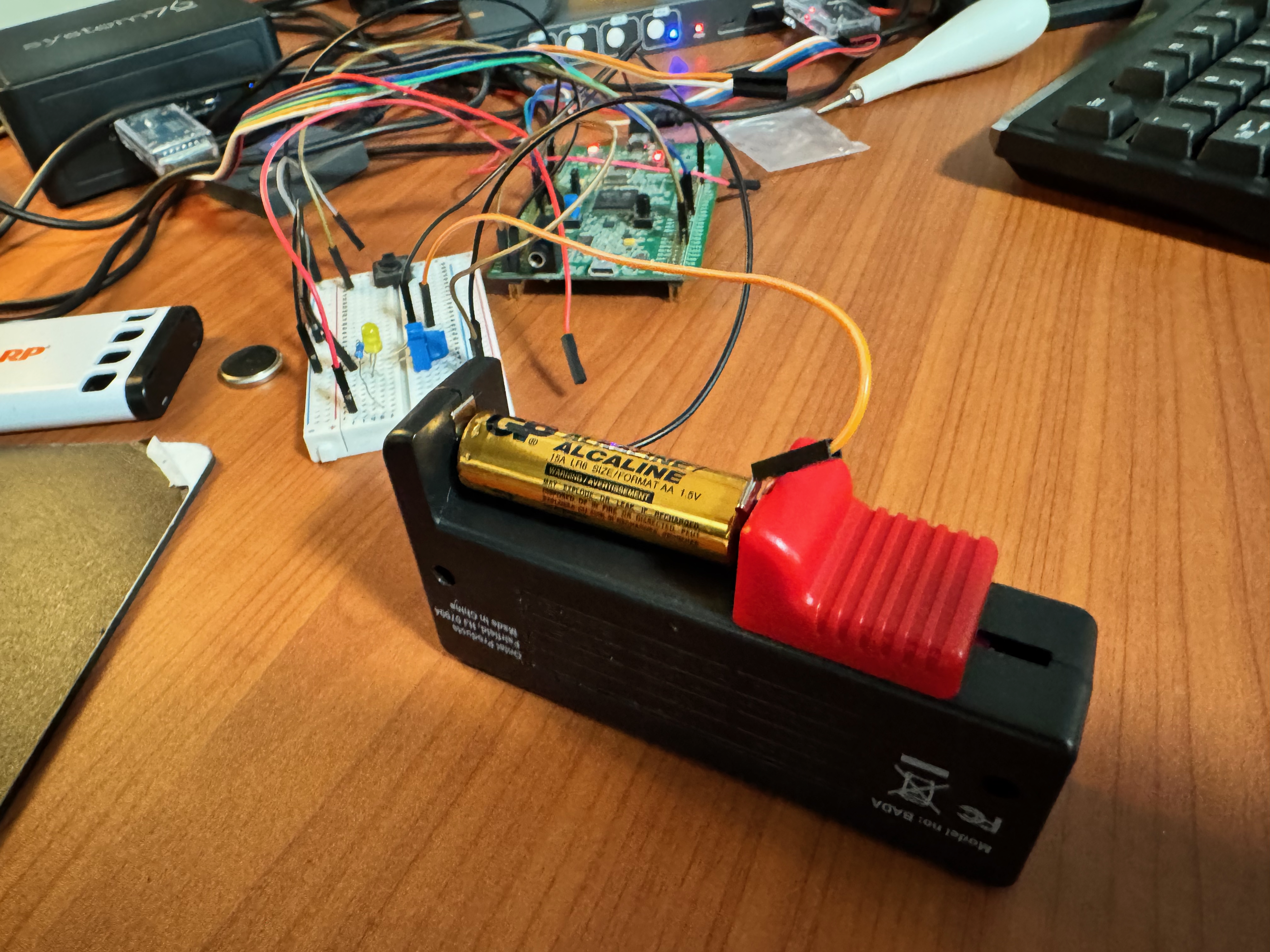
The battery voltage may be more or less stable but over a long time, the terminal voltage will be lower and will probably eventually go to 0 Volts.
amazon basics AA battery (Battery daddy setup)
01:01:39 -I- [batt  ] :  batv=  2068 batvF=  1.6
01:01:40 -I- [batt  ] :  batv=  2074 batvF=  1.6
01:01:41 -I- [batt  ] :  batv=  2074 batvF=  1.6
01:01:42 -I- [batt  ] :  batv=  2072 batvF=  1.6
01:01:43 -I- [batt  ] :  batv=  2080 batvF=  1.6
01:01:44 -I- [batt  ] :  batv=  2072 batvF=  1.6
01:01:45 -I- [batt  ] :  batv=  2066 batvF=  1.6
01:01:46 -I- [batt  ] :  batv=  2076 batvF=  1.6
01:01:47 -I- [batt  ] :  batv=  2074 batvF=  1.6
01:01:48 -I- [batt  ] :  batv=  2066 batvF=  1.6
The voltage while stable is misleading. The battery holder arrangement was not the most robust. No factory calibration of the ADC was used in the above. The assumptions we made to compute the interpolation equation are also somewhat arbitrary and approximate.
8.1.4.3 Potentiometer
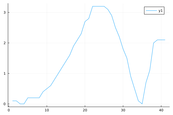
A potentiometer is a little more interesting. With the ability to move the tap, it is easy to see the ADC responding with a range of values - not just a static value.
8.1.4.4 Fader
Even more interesting is to generate a varying voltage to feed into the ADC. To achieve this, it is straightforward to use an Arduino UNO. In this case we adapt the fader example adding a capacitor to smooth out the variations - thus generating a stable voltage. The ADC pin is now connected to this output.
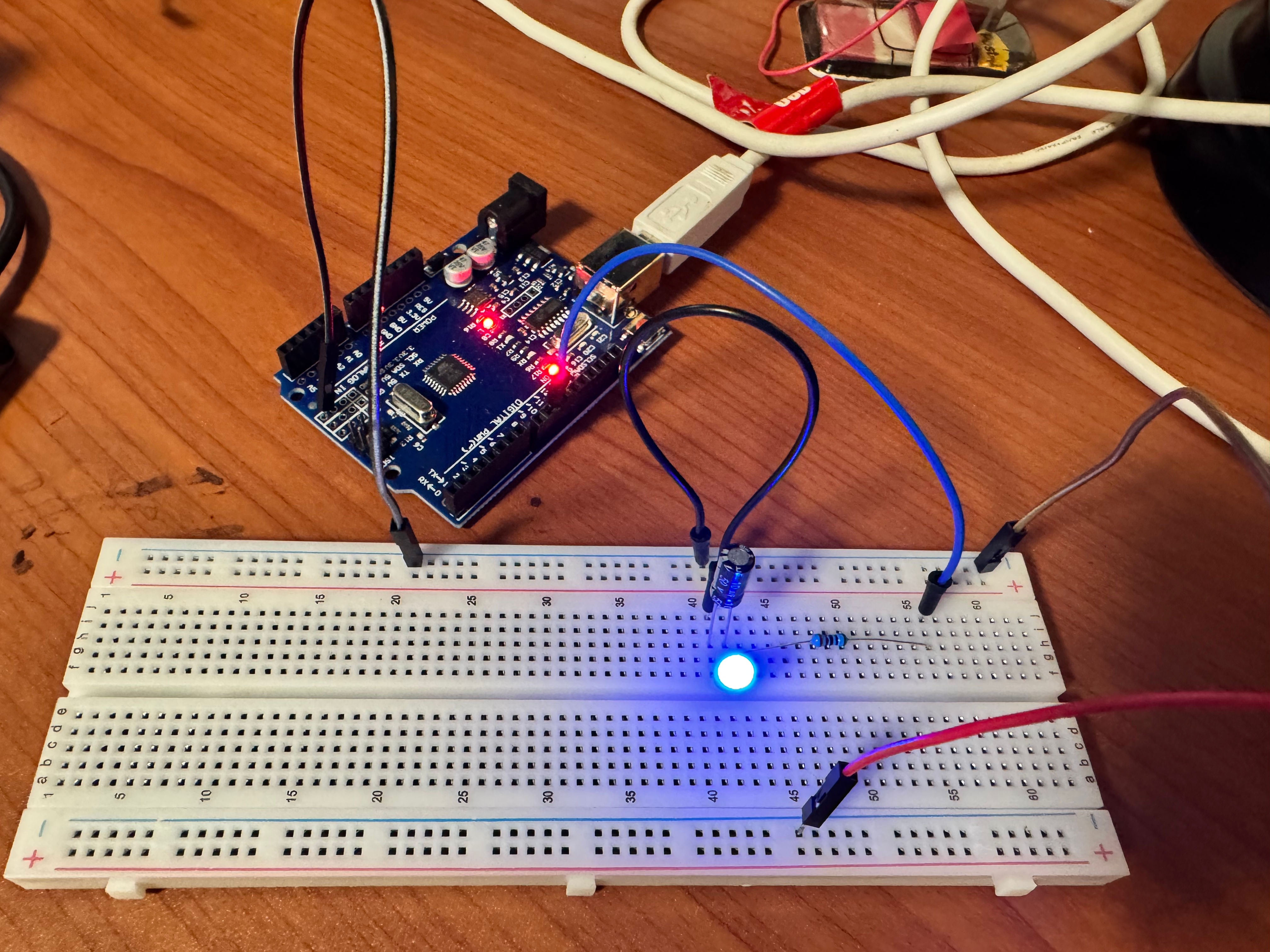
And now the application reads a varying voltage and plotting the voltages yields:
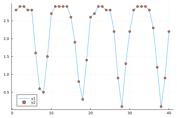
Please note that the fader operates with 30 millisecond gap while the digitizer operates at 1 Hz.
8.2 Development Insights
Analog to Digital conversion is perhaps the most critical component of any embedded system. The challenge of dealing with the physics (or any other natural phenomena) starts with sensing and converting the result to a digital form. While most development kits incorporate an ADC, production devices will need a higher quality converter. Sampling rate, compensation for ambient temperature, dealing with supply voltage jitter are some of the challenges that will determine the success of the device - leading to the choice of specialized ADCs.
Sampling the ambient room temperature for example may be reasonable at 1Hz or even slower for a residential thermostat. An EKG on the other hand will benefit from higher sample rates say 1KHz in order to truly represent the physiology. Similar arguments may lead to a 24 bit width digitization for the latter while 8 bits may be sufficient for the temperature.
It is also likely that an external ADC will provide an I2C or SPI interface leaving the microcontroller free from the numerous low level details.